H8-FP
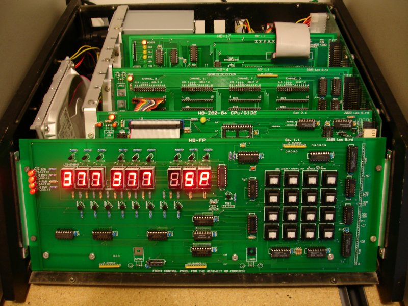
Here are some photos of a fully assembled and installed
front control panel along with some construction notes.
The front panel in this photo is being used in a system
powered by a MicroATX 320 watt power supply which is plugged
into my redesigned backplane/motherboard. No voltage
regulators are needed in any of the installed cards because
of the regulated power source from the MicroATX power
supply. When using this setup a bare wire should be soldered
between the voltage-in and voltage-out pads of all PCBs for
all regulators (the center pad is GND and should be left
unused).
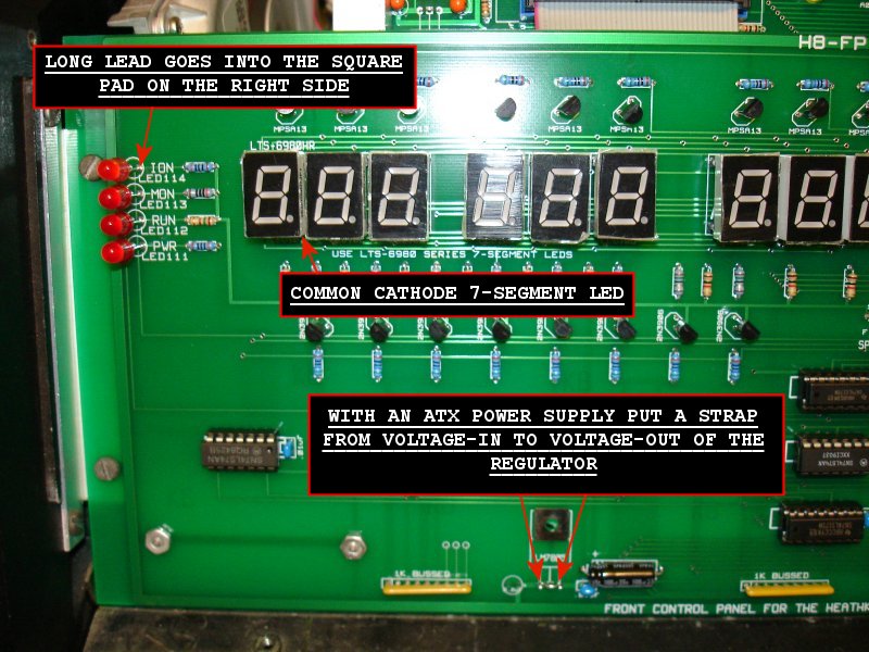
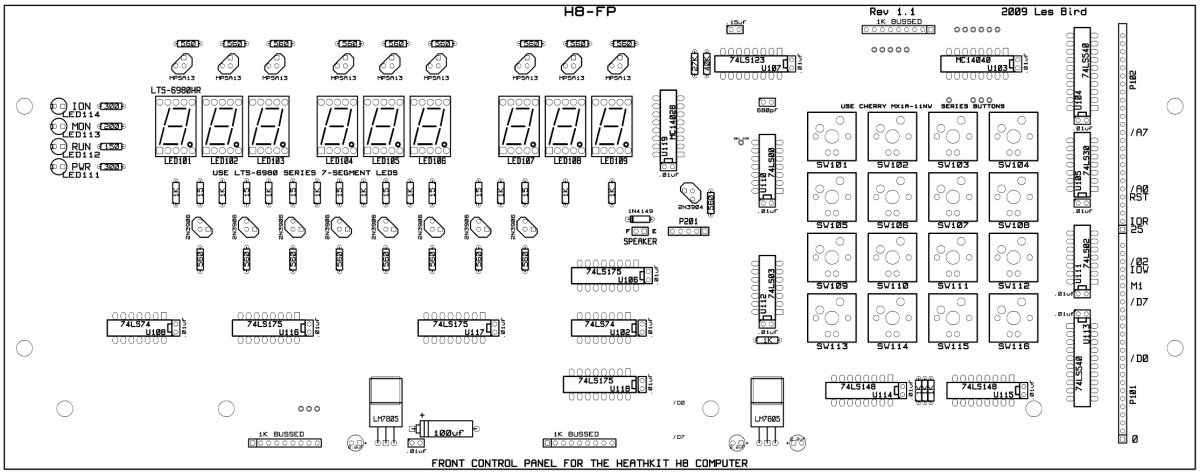
For the power LEDs on the left side the long lead should be soldered into the square pad on the PCB which is on the right side. Use common cathode 7-segment LEDs for the display in either .5" or .56" sizes. Any brand and color will work but if you're using the red plastic overlay with the standard H8 front panel cover you should use red colored LEDs.
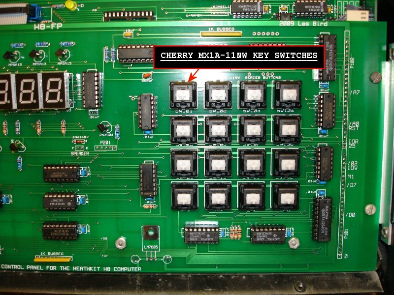
Use Cherry MX1A series key switches. The key switches and key caps (in a variety of colors) can be ordered from X-Keys (www.x-keys.com).
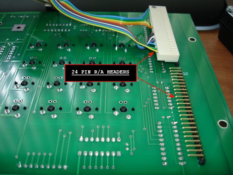
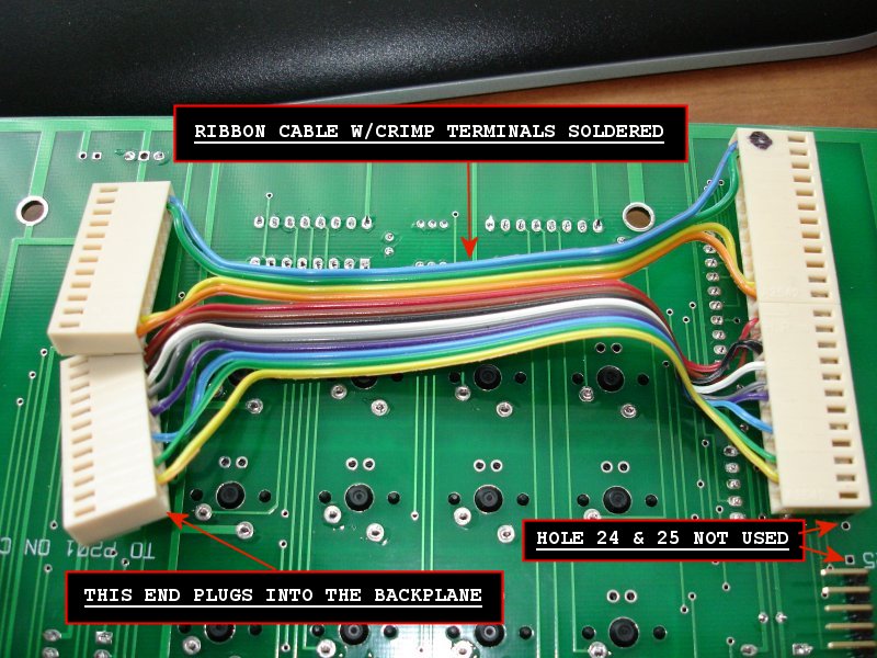
My recommendation for the interface to the backplane is to use right-angle 24 pin headers as shown below (holes 24 and 25 are not used). Another method is to just solder the ribbon cable directly to the front control panel (instead of the headers) and use crimp terminals and a crimp terminal housing on the other end for plugging into the backplane.
A ribbon cable needs to be assembled by soldering crimp terminals to the ends and inserting them into crimp terminal housings. On the lower half you should use pins 0, 1, 10 thru 17, 19, 21 and 22. On the upper half wires should be plugged into pins 26, 29 thru 37, 48 and 49. The Heath company uses 0-based numbering for the H-8 buss so pin 0 is on the bottom and pin 49 is at the top.
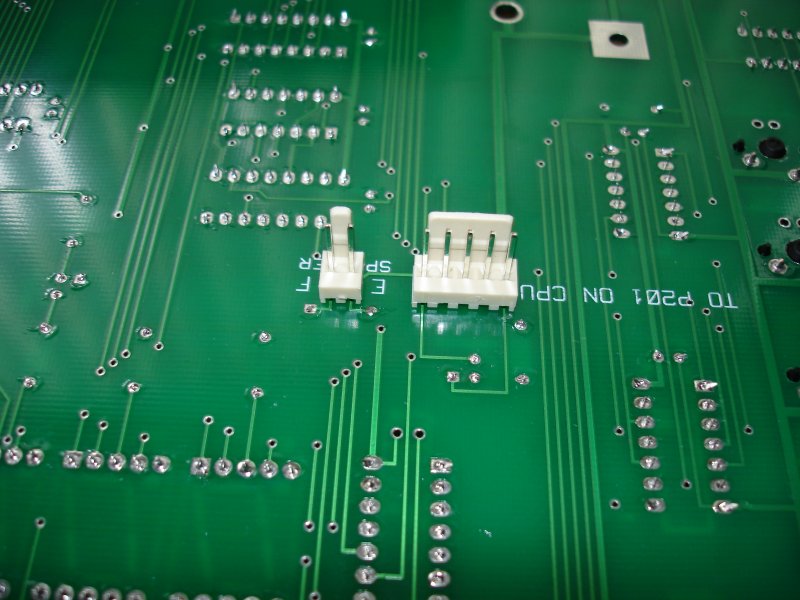
The interface to the CPU board uses a 5-pin plug. I chose to use a friction lock header as shown in this photo but I highly recommend using a right-angle header instead. With the straight header it is an extremely tight fit with the CPU board installed directly behind the front control panel. I also use a 2-pin friction lock header for the speaker hook up and again I recommend using a right-angle header. Use a straight 5 wire ribbon cable from the front panel to P201 on the CPU board. For the speaker hook up just use 2 wires soldered or plugged onto the terminals of an unamplified speaker. These connectors are located on the backside of the front panel PCB.
The rest of the construction for the front control panel is pretty simple. Just follow the PCB silkscreen for installing ICs, transistors and other components.
PCBS Home Page
October 1, 2009